Configuration Etherchannel
26-1 EtherChannel Configuration – Lab Exercise
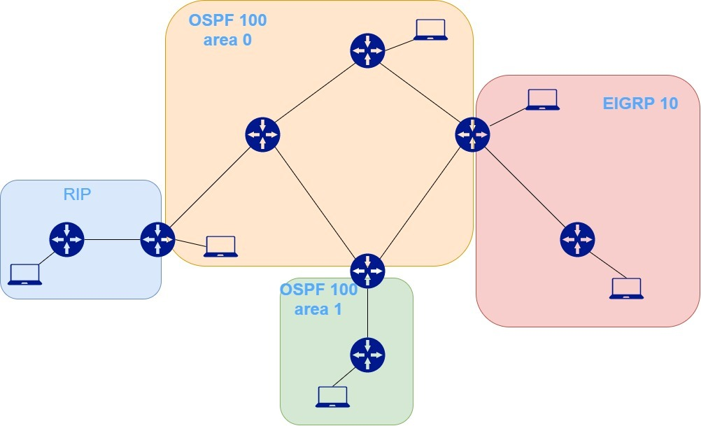
Lab Topology

LACP EtherChannel Configuration
The access layer switches Acc3 and Acc4 both have two FastEthernet uplinks. How much total bandwidth is available between the PCs attached to Acc3 and the PCs attached to Acc4?
Port yang digunakan adalah FastEthernet maka total bandwidth yang tersedia adalah 200Mbps.
Convert the existing uplinks from Acc3 to CD1 and CD2 to LACP EtherChannel. Configure descriptions on the port channel interfaces to help avoid confusion later.
Acc3(config)#int range f0/23-24
Acc3(config-if-range)#channel-group 1 mode active
Acc3(config-if-range)#
Creating a port-channel interface Port-channel 1
Acc3(config-if-range)#exit
Acc3(config)#int port-channel 1
Acc3(config-if)#desc Link to CD1
Acc3(config-if)#switchport mode trunk
Acc3(config-if)#switchport trunk native vlan 199
Notes:
Untuk mengimplementasikan Etherchannel, maka kita harus memilih port mana saja yang akan dibundling yg kemudian menjadi etherchannel. Pada soal ini sudah ditentukan yaitu interface f0/23 dan f0/24 ke arah switch CD1. Maka pertama2 kita akses range interface f0/23-24, kemudian aktifkan channel-group 1 mode active. Untuk dynamic etherchannel jenis LACP, maka modenya antara active atau passive. Selanjutnya switch secara otomatis akan membangun suatu virtual interface yaitu port-channel 1. Port-channel 1 ini terdiri dari interface yang kita aktifkan channel-group nya yaitu interface f0/23 dan f0/24 yang secara logical dijadikan 1 interface.
Kemudian kita akses interface port-channel 1, kita diminta untuk membuat deskripsi dari port ini. Cukup dengan command description diikuti dengan deskripsi yang diinginkan. Etherchannel biasanya menggunakan switchport mode trunk. Optional kita tambahkan switchport trunk native vlan 199.
CD1(config)#int range f0/23-24
CD1(config-if-range)#channel-group 1 mode active
CD1(config-if-range)#
Creating a port-channel interface Port-channel 1
CD1(config-if-range)#exit
CD1(config)#int port-channel 1
CD1(config-if)#desc Link to Acc3
CD1(config-if)#switchport mode trunk
CD1(config-if)#switchport trunk native vlan 199
Notes:
Jangan lupa untuk membuat etherchannel pada lawan dari interface yang sudah kita buat etherchannel sebelumnya. Interface pada soal ini sudah disamakan dengan interface pada switch sebelumnya yaitu f0/23 dan f0/24. Untuk commandnya tidak ada perubahan, hanya pada description-nya saja.
Acc3(config)#int range f0/21-22
Acc3(config-if-range)#channel-group 2 mode active
Creating a port-channel interface Port-channel 2
Acc3(config-if-range)#exit
Acc3(config)#int port-channel 2
Acc3(config-if)#desc Link to CD2
Acc3(config-if)#switchport mode trunk
Acc3(config-if)#switchport trunk native vlan 199
CD2(config)#int range f0/21-22
CD2(config-if-range)#channel-group 2 mode active
Creating a port-channel interface Port-channel 2
CD2(config-if-range)#exit
CD2(config)#int port-channel 2
CD2(config-if)#desc Link to Acc3
CD2(config-if)#switchport mode trunk
CD2(config-if)#switchport trunk native vlan 199
Verify the EtherChannels come up.
Acc3#show etherchannel summary
Flags: D - down P - in port-channel
I - stand-alone s - suspended
H - Hot-standby (LACP only)
R - Layer3 S - Layer2
U - in use f - failed to allocate aggregator
u - unsuitable for bundling
w - waiting to be aggregated
d - default port
Number of channel-groups in use: 2
Number of aggregators: 2
Group Port-channel Protocol Ports
------+-------------+-----------+----------------------------------------------
1 Po1(SU) LACP Fa0/23(P) Fa0/24(P)
2 Po2(SU) LACP Fa0/21(P) Fa0/22(P)
CD1#show etherchannel summary
Flags: D - down P - in port-channel
I - stand-alone s - suspended
H - Hot-standby (LACP only)
R - Layer3 S - Layer2
U - in use f - failed to allocate aggregator
u - unsuitable for bundling
w - waiting to be aggregated
d - default port
Number of channel-groups in use: 1
Number of aggregators: 1
Group Port-channel Protocol Ports
------+-------------+-----------+----------------------------------------------
1 Po1(SU) LACP Fa0/23(P) Fa0/24(P)
CD2#show etherchannel summary
Flags: D - down P - in port-channel
I - stand-alone s - suspended
H - Hot-standby (LACP only)
R - Layer3 S - Layer2
U - in use f - failed to allocate aggregator
u - unsuitable for bundling
w - waiting to be aggregated
d - default port
Number of channel-groups in use: 1
Number of aggregators: 1
Group Port-channel Protocol Ports
------+-------------+-----------+----------------------------------------------
2 Po2(SU) LACP Fa0/21(P) Fa0/22(P)
CD2#show etherchannel summary
Flags: D - down P - in port-channel
I - stand-alone s - suspended
H - Hot-standby (LACP only)
R - Layer3 S - Layer2
U - in use f - failed to allocate aggregator
u - unsuitable for bundling
w - waiting to be aggregated
d - default port
Number of channel-groups in use: 1
Number of aggregators: 1
Group Port-channel Protocol Ports
------+-------------+-----------+----------------------------------------------
1 Po2(SU) LACP Fa0/21(P) Fa0/22(P)
PAgP EtherChannel Configuration
Convert the existing uplinks from Acc4 to CD1 and CD2 to PAgP EtherChannel. (Note that in a real world environment you should always use LACP if possible.)
Acc4(config)#int range f0/23-24
Acc4(config-if-range)#channel-group 1 mode desirable
Creating a port-channel interface Port-channel 1
Acc4(config-if-range)#exit
Acc4(config)#int port-channel 1
Acc4(config-if)#desc Link to CD2
Acc4(config-if)#switchport mode trunk
Acc4(config-if)#switchport trunk native vlan 199
Notes:
Tidak ada perbedaan yang signifikan dibanding dengan Dynamic Ethercannel LACP. Untuk mengimplementasikan etherchannel PAgP, cukup dengan command mode desirable atau mode auto.
LACP disarankan apabila terdapat perangkat selain Cisco. PAgP khusus untuk perangkat Cisco saja.
CD2(config)#int range f0/23-24
CD2(config-if-range)#channel-group 1 mode desirable
Creating a port-channel interface Port-channel 1
CD2(config-if-range)#exit
CD2(config)#int port-channel 1
CD2(config-if)#desc Link to Acc4
CD2(config-if)#switchport mode trunk
CD2(config-if)#switchport trunk native vlan 199
Acc4(config)#int range f0/21-22
Acc4(config-if-range)#channel-group 2 mode desirable
Creating a port-channel interface Port-channel 2
Acc4(config-if-range)#exit
Acc4(config)#int port-channel 2
Acc4(config-if)#desc Link to CD1
Acc4(config-if)#switchport mode trunk
Acc4(config-if)#switchport trunk native vlan 199
CD1(config)#int range f0/21-22
CD1(config-if-range)#channel-group 2 mode desirable
Creating a port-channel interface Port-channel 2
CD1(config-if-range)#exit
CD1(config)#int port-channel 2
CD1(config-if)#desc Link to Acc4
CD1(config-if)#switchport mode trunk
CD1(config-if)#switchport trunk native vlan 199
Verify the EtherChannels come up.
Acc4#
%SYS-5-CONFIG_I: Configured from console by console
Acc4#show etherchannel summary
Flags: D - down P - in port-channel
I - stand-alone s - suspended
H - Hot-standby (LACP only)
R - Layer3 S - Layer2
U - in use f - failed to allocate aggregator
u - unsuitable for bundling
w - waiting to be aggregated
d - default port
Number of channel-groups in use: 2
Number of aggregators: 2
Group Port-channel Protocol Ports
------+-------------+-----------+----------------------------------------------
1 Po1(SU) PAgP Fa0/23(P) Fa0/24(P)
2 Po2(SU) PAgP Fa0/21(P) Fa0/22(P)
CD2#show etherchannel summary
Flags: D - down P - in port-channel
I - stand-alone s - suspended
H - Hot-standby (LACP only)
R - Layer3 S - Layer2
U - in use f - failed to allocate aggregator
u - unsuitable for bundling
w - waiting to be aggregated
d - default port
Number of channel-groups in use: 2
Number of aggregators: 2
Group Port-channel Protocol Ports
------+-------------+-----------+----------------------------------------------
1 Po1(SU) PAgP Fa0/23(P) Fa0/24(P)
2 Po2(SU) LACP Fa0/21(P) Fa0/22(P)
CD1#show etherchannel summary
Flags: D - down P - in port-channel
I - stand-alone s - suspended
H - Hot-standby (LACP only)
R - Layer3 S - Layer2
U - in use f - failed to allocate aggregator
u - unsuitable for bundling
w - waiting to be aggregated
d - default port
Number of channel-groups in use: 2
Number of aggregators: 2
Group Port-channel Protocol Ports
------+-------------+-----------+----------------------------------------------
1 Po1(SU) LACP Fa0/23(P) Fa0/24(P)
2 Po2(SU) PAgP Fa0/21(P) Fa0/22(P)
Static EtherChannel Configuration
Convert the existing uplinks between CD1 and CD2 to static EtherChannel.
CD1(config)#int range g0/1-2
CD1(config-if-range)#channel-group 3 mode on
CD1(config-if-range)#exit
CD1(config)#int port-channel 3
CD1(config-if)#desc Link to CD3
CD1(config-if)#switchport mode trunk
CD1(config-if)#switchport trunk native vlan 199
Notes:
Tidak ada perbedaan yang signifikan dibanding dengan mode dynamic. Mode Static dapat diaktifkan dengan menggunakan command mode on atau mode off saja.
CD2(config)#int range g0/1-2
CD2(config-if-range)#channel-group 3 mode on
CD2(config-if-range)#
Creating a port-channel interface Port-channel 3
CD2(config-if-range)#exit
CD2(config)#int port-channel 3
CD2(config-if)#desc Link to CD1
CD2(config-if)#switchport mode trunk
CD2(config-if)#switchport trunk native vlan 199
Verify the EtherChannel comes up.
CD1#show etherchannel summary
Flags: D - down P - in port-channel
I - stand-alone s - suspended
H - Hot-standby (LACP only)
R - Layer3 S - Layer2
U - in use f - failed to allocate aggregator
u - unsuitable for bundling
w - waiting to be aggregated
d - default port
Number of channel-groups in use: 3
Number of aggregators: 3
Group Port-channel Protocol Ports
------+-------------+-----------+----------------------------------------------
1 Po1(SU) LACP Fa0/23(P) Fa0/24(P)
2 Po2(SU) PAgP Fa0/21(P) Fa0/22(P)
3 Po3(SU) - Gig0/1(P) Gig0/2(P)
CD2#show etherchannel summary
Flags: D - down P - in port-channel
I - stand-alone s - suspended
H - Hot-standby (LACP only)
R - Layer3 S - Layer2
U - in use f - failed to allocate aggregator
u - unsuitable for bundling
w - waiting to be aggregated
d - default port
Number of channel-groups in use: 3
Number of aggregators: 3
Group Port-channel Protocol Ports
------+-------------+-----------+----------------------------------------------
1 Po1(SU) PAgP Fa0/23(P) Fa0/24(P)
2 Po2(SU) LACP Fa0/21(P) Fa0/22(P)
3 Po3(SU) - Gig0/1(P) Gig0/2(P)
How much total bandwidth is available between the PCs attached to Acc3 and the PCs attached to Acc4 now?
2 port sekaligus dengan kecepatan 100Mbps, maka total bandwidth yang tersedia adalah 200Mbps.
Layer 3 EtherChannel Configuration
The Layer 3 switches Switch1, Switch2 and Switch3 are physically separate from the switches you configured earlier in this lab exercise.

Switch1 and Switch2 are connected together with their GigabitEthernet1/0/1 and 1/0/2 interfaces.
Configure these interfaces as a Layer 3 Etherchannel with LACP. Configure IP address 192.168.0.1/30 on Switch1 and 192.168.0.2/30 on Switch2.
Switch1(config)#int range g1/0/1-2
Switch1(config-if-range)#no switchport
Switch1(config-if-range)#channel-group 1 mode active
Switch1(config-if-range)#
Creating a port-channel interface Port-channel 1
Switch1(config-if-range)#exit
Switch1(config)#int port-channel 1
Switch1(config-if)#ip add 192.168.0.1 255.255.255.252
Notes:
Sama seperti sebelumnya, disini kita mengakses interface G1/0/1 dan G1/0/2. Namun harus diingat bahwa Switch di sini yang digunakan adalah Switch Layer 3.
Secara default, semua interface pada switch layer 3 belum bisa ditambahkan IP address karena masih berfungsi sebagai layer 2. Untuk mengubahnya menjadi layer 3, maka kita akses interface yang diinginkan kemudian masukan command no switchport.
Selanjutnya buat port-channel layer 3 tersebut dengan command channel group 1 mode active.
Lalu kita akses interface port-channel 1, dan masukkan ip address nya.
Switch2(config)#int range g1/0/1-2
Switch2(config-if-range)#no switchport
Switch2(config-if-range)#channel-group 1 mode active
Switch2(config-if-range)#
Creating a port-channel interface Port-channel 1
Switch2(config-if-range)#exit
Switch2(config)#int port-channel 1
Switch2(config-if)#ip add 192.168.0.2 255.255.255.252
Switch1 and Switch3 are connected together with their GigabitEthernet1/0/3 and 1/0/4 interfaces.
Configure these interfaces as a Layer 3 Etherchannel with LACP. Configure IP address 192.168.0.5/30 on Switch1 and 192.168.0.6/30 on Switch3.
Switch1(config)#int range g1/0/3-4
Switch1(config-if-range)#no switchport
Switch1(config-if-range)#channel-group 2 mode active
Switch1(config-if-range)#
Creating a port-channel interface Port-channel 2
Switch1(config-if-range)#exit
Switch1(config)#int port-channel 2
Switch1(config-if)#ip add 192.168.0.5 255.255.255.252
Switch3(config)#int range g1/0/3-4
Switch3(config-if-range)#no switchport
Switch3(config-if-range)#channel-group 2 mode active
Switch3(config-if-range)#
Creating a port-channel interface Port-channel 2
Switch3(config-if-range)#exit
Switch3(config)#int port-channel 2
Switch3(config-if)#ip add 192.168.0.6 255.255.255.252
Switch2 and Switch3 are connected together with their GigabitEthernet1/0/5 and 1/0/6 interfaces.
Configure these interfaces as a Layer 3 Etherchannel with LACP. Configure IP address 192.168.0.9/30 on Switch2 and 192.168.0.10/30 on Switch3.
Switch2(config)#int range g1/0/5-6
Switch2(config-if-range)#no switchport
Switch2(config-if-range)#channel-group 3 mode active
Switch2(config-if-range)#
Creating a port-channel interface Port-channel 3
Switch2(config-if-range)#exit
Switch2(config)#int port-channel 3
Switch2(config-if)#ip add 192.168.0.9 255.255.255.252
Switch3(config)#int range g1/0/5-6
Switch3(config-if-range)#no switchport
Switch3(config-if-range)#channel-group 3 mode active
Switch3(config-if-range)#
Creating a port-channel interface Port-channel 3
Switch3(config-if-range)#exit
Switch3(config)#int port-channel 3
Switch3(config-if)#ip add 192.168.0.10 255.255.255.252
Verify the EtherChannels come up.
Switch1#show etherchannel summary
Flags: D - down P - in port-channel
I - stand-alone s - suspended
H - Hot-standby (LACP only)
R - Layer3 S - Layer2
U - in use f - failed to allocate aggregator
u - unsuitable for bundling
w - waiting to be aggregated
d - default port
Number of channel-groups in use: 2
Number of aggregators: 2
Group Port-channel Protocol Ports
------+-------------+-----------+----------------------------------------------
1 Po1(RU) LACP Gig1/0/1(P) Gig1/0/2(P)
2 Po2(RU) LACP Gig1/0/3(P) Gig1/0/4(P)
Switch2#show etherchannel summary
Flags: D - down P - in port-channel
I - stand-alone s - suspended
H - Hot-standby (LACP only)
R - Layer3 S - Layer2
U - in use f - failed to allocate aggregator
u - unsuitable for bundling
w - waiting to be aggregated
d - default port
Number of channel-groups in use: 2
Number of aggregators: 2
Group Port-channel Protocol Ports
------+-------------+-----------+----------------------------------------------
1 Po1(RU) LACP Gig1/0/1(P) Gig1/0/2(P)
3 Po3(RU) LACP Gig1/0/5(P) Gig1/0/6(P)
Switch3#show etherchannel summary
Flags: D - down P - in port-channel
I - stand-alone s - suspended
H - Hot-standby (LACP only)
R - Layer3 S - Layer2
U - in use f - failed to allocate aggregator
u - unsuitable for bundling
w - waiting to be aggregated
d - default port
Number of channel-groups in use: 2
Number of aggregators: 2
Group Port-channel Protocol Ports
------+-------------+-----------+----------------------------------------------
2 Po2(RU) LACP Gig1/0/3(P) Gig1/0/4(P)
3 Po3(RU) LACP Gig1/0/5(P) Gig1/0/6(P)
Configure Switch1, Switch2 and Switch3 to advertise the IP subnets configured on their Etherchannel interfaces in OSPF Area 0.
Switch1(config)#int port-channel 1
Switch1(config-if)#ip ospf 1 area 0
Switch1(config-if)#exit
Switch1(config)#int port-channel 2
Switch1(config-if)#ip ospf 1 area 0
Switch2(config)#int port-channel 1
Switch2(config-if)#ip ospf 1 area 0
Switch2(config-if)#exit
Switch2(config)#int port-channel 3
Switch2(config-if)#ip ospf 1 area 0
Switch3(config)#int port-channel 2
Switch3(config-if)#ip ospf 1 area 0
Switch2(config-if)#exit
Switch3(config-if)#int port-channel 3
Switch3(config-if)#ip ospf 1 area 0
Notes:
OSPF dapat diimplementasikan salah satunya dengan menentukan interface mana yang akan dijadikan protocol OSPF. Di sini, saya mengaktifkan OSPF menggunakan masing-masing port-channel dengan mengakses port-channel nya dahulu, diikuti dengan command ip ospf 1 area 0.
Verify the OSPF adjacencies are formed successfully.
Switch1#show ip ospf neighbor
Neighbor ID Pri State Dead Time Address Interface
192.168.0.9 1 FULL/BDR 00:00:31 192.168.0.2 Port-channel1
192.168.0.10 1 FULL/BDR 00:00:39 192.168.0.6 Port-channel2
Switch2#show ip ospf neighbor
Neighbor ID Pri State Dead Time Address Interface
192.168.0.10 1 FULL/DR 00:00:36 192.168.0.10 Port-channel3
192.168.0.5 1 FULL/DR 00:00:38 192.168.0.1 Port-channel1
Switch3#show ip ospf neighbor
Neighbor ID Pri State Dead Time Address Interface
192.168.0.9 1 FULL/BDR 00:00:38 192.168.0.9 Port-channel3
192.168.0.5 1 FULL/DR 00:00:37 192.168.0.5 Port-channel2
Verify Switch1, Switch2 and Switch3 have routes to all configured networks in their routing tables.
Switch1#sh ip route | begin Gate
Gateway of last resort is not set
192.168.0.0/30 is subnetted, 3 subnets
C 192.168.0.0 is directly connected, Port-channel1
C 192.168.0.4 is directly connected, Port-channel2
O 192.168.0.8 [110/2] via 192.168.0.2, 00:00:30, Port-channel1
[110/2] via 192.168.0.6, 00:00:30, Port-channel2
Switch2#show ip route | begin Gate
Gateway of last resort is not set
192.168.0.0/30 is subnetted, 3 subnets
C 192.168.0.0 is directly connected, Port-channel1
O 192.168.0.4 [110/2] via 192.168.0.1, 00:01:00, Port-channel1
[110/2] via 192.168.0.10, 00:01:00, Port-channel3
C 192.168.0.8 is directly connected, Port-channel3
Switch3#show ip route | begin Gate
Gateway of last resort is not set
192.168.0.0/30 is subnetted, 3 subnets
O 192.168.0.0 [110/2] via 192.168.0.5, 00:01:51, Port-channel2
[110/2] via 192.168.0.9, 00:01:51, Port-channel3
C 192.168.0.4 is directly connected, Port-channel2
C 192.168.0.8 is directly connected, Port-channel3
Which physical ports on which switches do you expect the Spanning Tree protocol to disable? Verify this.
Spanning Tree hanya dapat aktif pada interface dengan layer 2.
Switch1#show spanning-tree
No spanning tree instance exists.
Source: www.flackbox.com
Comments
Post a Comment